Mitch Richling: Minati-Frasca Double-scroll Circuit
A SPICEy adventure with a little extra chaos!
| Author: | Mitch Richling |
| Updated: | 2023-01-29 |
Table of Contents
1. Introduction
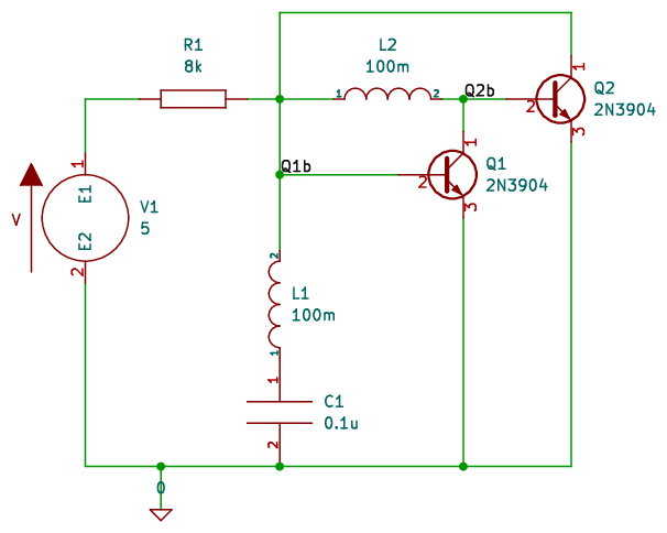
The circuit below is from page 109 of the excellent book "Elegant Circuits: Simple Chaotic Oscillators" by Julien Clinton Sprott & Wesley Joo-Chen Thio. This circuit is based upon on one from a 2017 paper entitled "Atypical transistor-based chaotic oscillators: Design, realization, and diversity" by Minati et al. Being one of the simplest circuits discovered capable of producing a multiscroll attractor made it interesting to Sprott et al. For me, I was attracted to the simple symmetry of the thing and just wanted to build it.
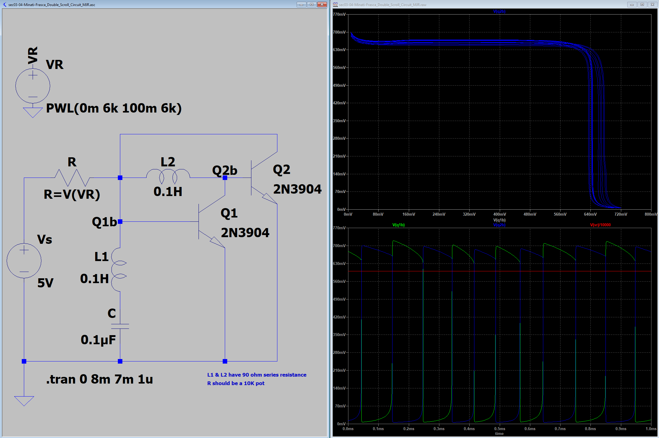
2. What we expect
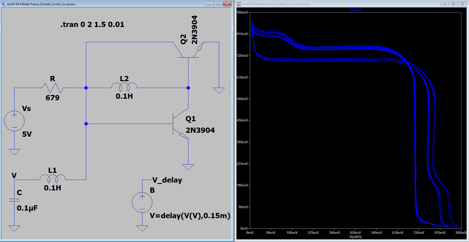
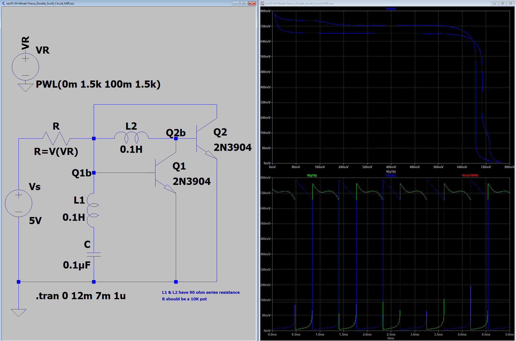
The following simulation shows the expected double scroll:
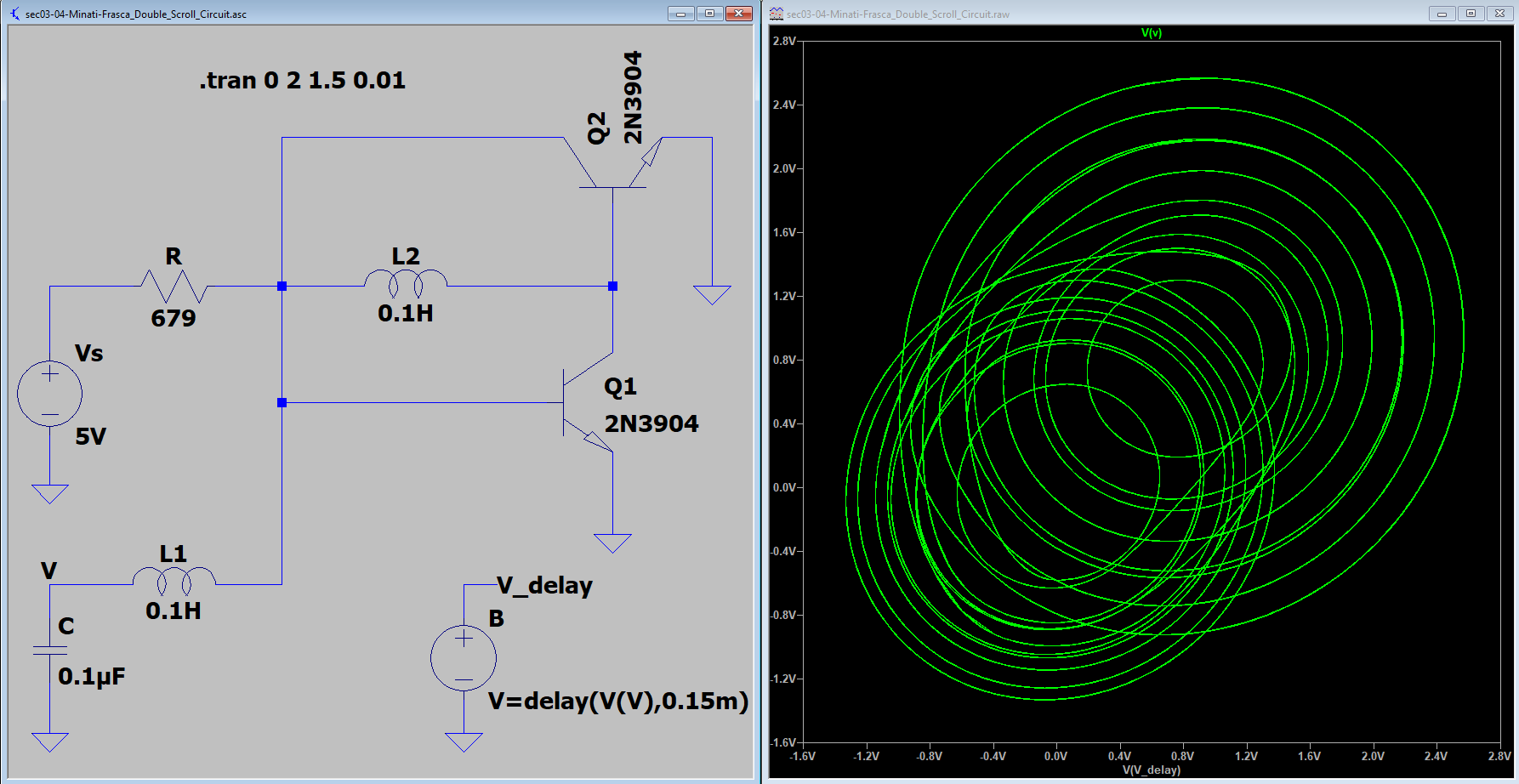
And here we have the transistor base voltages plotted against one another:
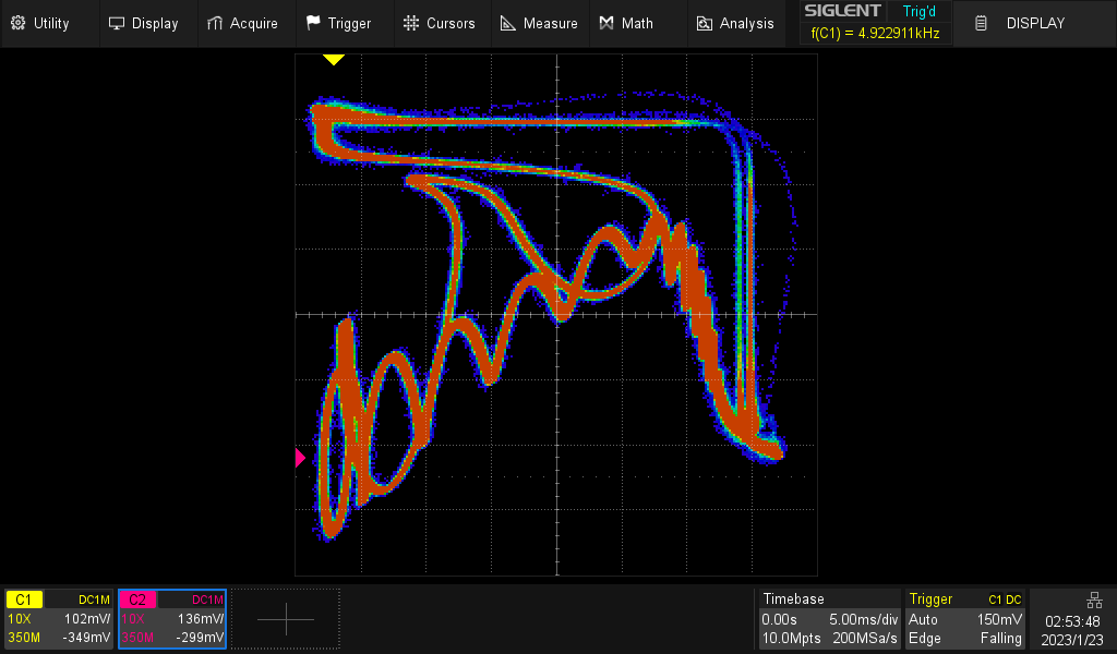
3. What we got
My prototype:
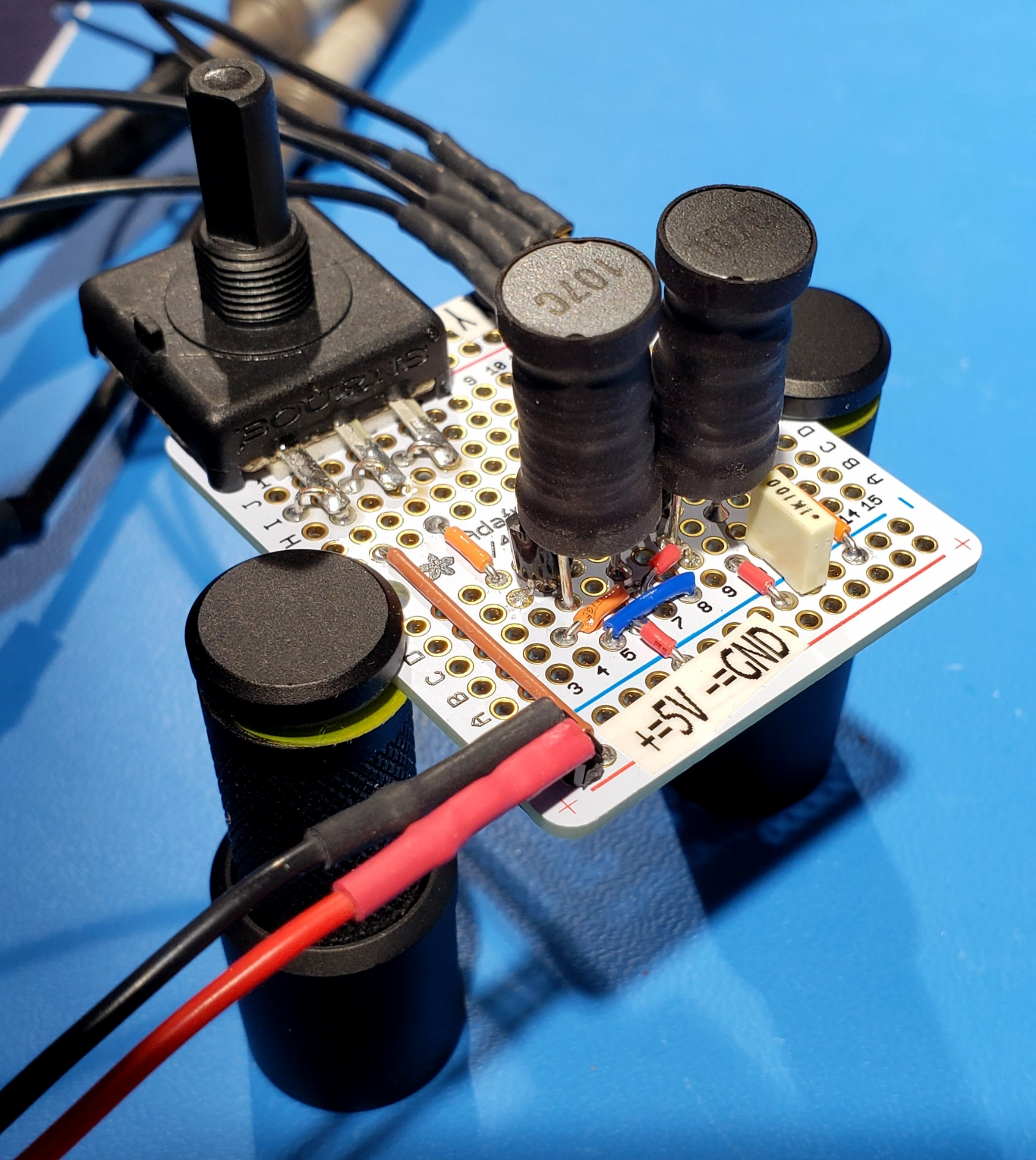
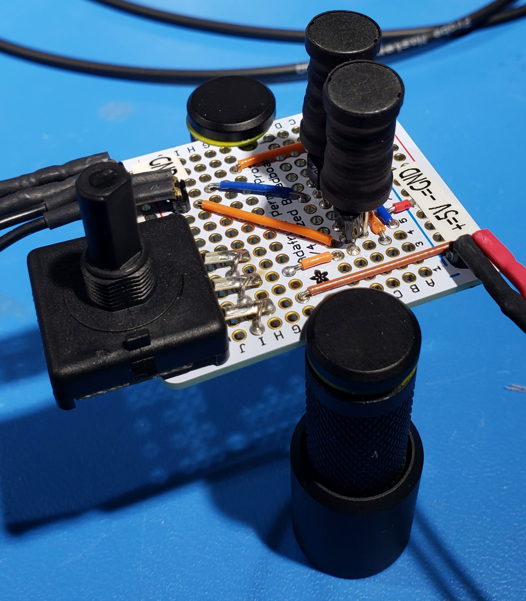
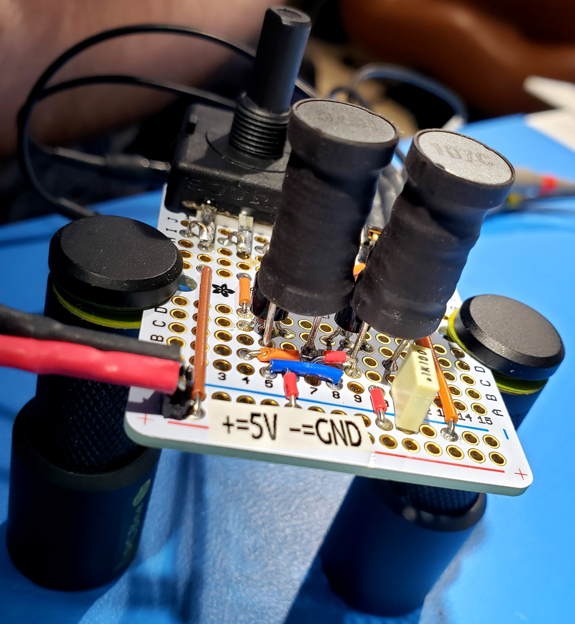
I used a 10K pot for the resistor in the circuit. And here is what we get on the scope:
Wow. It's perfect. Simulation and prototype match quite nicely. How about that!
4. But wait!!! More chaos that I expected!!!
The results in the previous section were perfect! But… Then I turned the pot…
That's not what we expected! I simulated for values of R from about 2k up to 10k, and the behavior is always this simple, "L" shape. After quite a bit of
playing around with SPICE, I was at a loss. So I put the computer to sleep and powered down the bench. When I came back to it in the morning, I powered on
the bench only to witness the scope displaying a perfect "L" shape where it had been all wonky the night before! So then I turned the pot, and the weirdness
came back. Apparently my bench is haunted…
Then I cut power to the circuit, and then turned it back on. No weirdness. The weirdness only occurs when I play with the pot while the circuit is under power! What fun! In particular, if I turn the pot down past a particular point, and then turn it higher I get weirdness. A little exploration shows us the circuit has two qualitatively different behaviors:
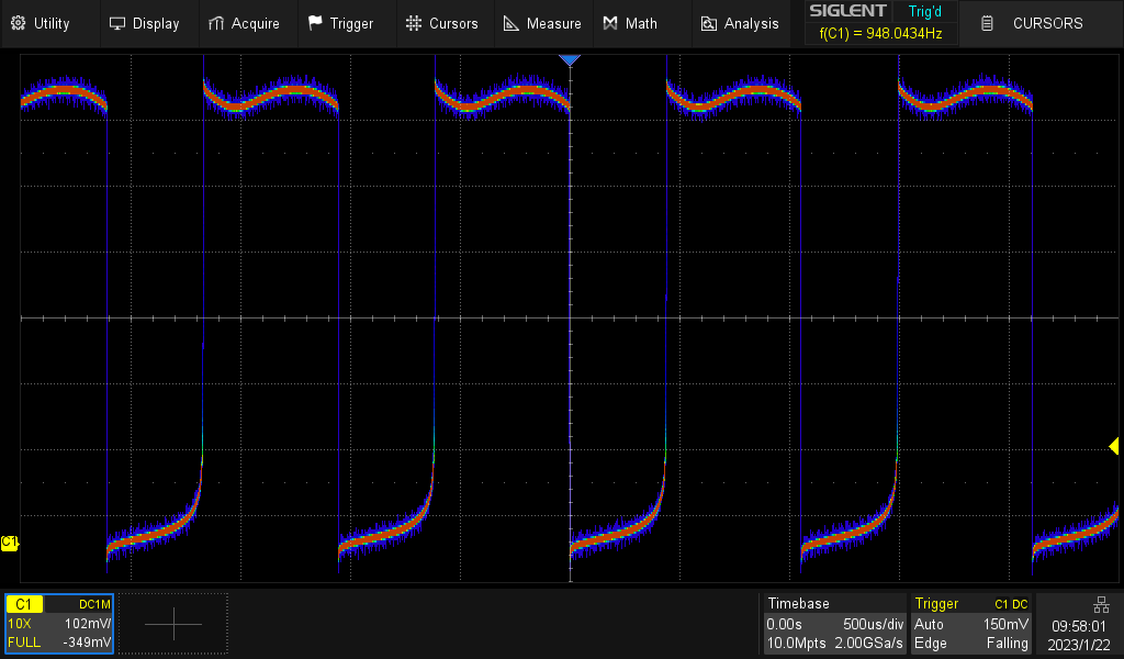 |
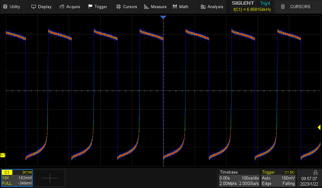 |
R < 2K |
R > 2K |
Notice the wavy tops of the voltage curve for low values of R, and the sawtooth-like tops for higher values of R. We
can see this in simulation too (click the images for larger versions):
 |
 |
R < 2K |
R > 2K |
But we only get weirdness when we move the pot from under 1.5K while the thing is powered up. We can simulate that!
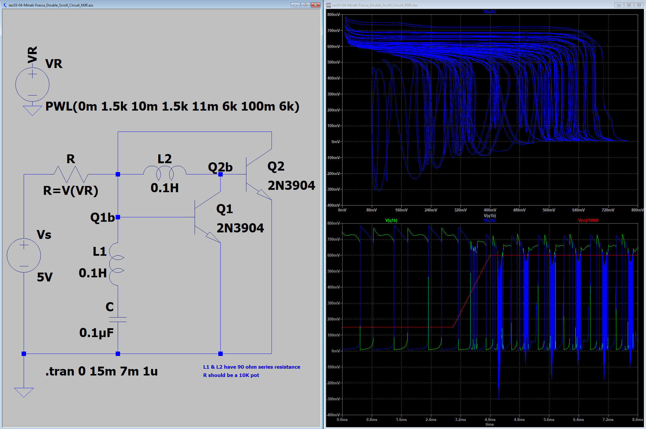
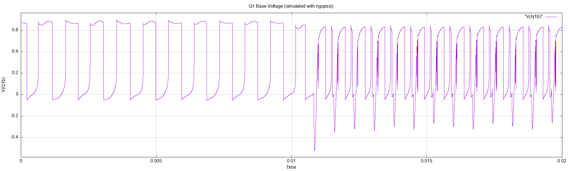
Just for fun, I wanted to see if I could get the same results with ngspice. One nice thing about ngspice is that we can simply set the resistor to a PWL
function like this: r=PWL(time, 0m, 1.5k, 10m, 1.5k, 11m, 6k, 100m, 6k). That's pretty sweet.
5. I'm so sensitive!
This circuit is a perfect example of something people like to call a "sensitive analog circuit". It's a member of a class of mythical creatures that strike fear and awe in the hearts of electronics practitioners. We like to think of our circuits as independent little things separate from the world in which they live; however, that is never the case. After all your little prototype is connected to your bench power supply, so all the electronics in that power supply are really part of your circuit now. Of course that power supply is plugged into the wall, so the entire power grid is really part of your circuit too. Shoot, even the air around your circuit is part of you circuit – it's a high value resistance connecting all the exposed metallic bits. This line of thought is a little silly, but sometimes the silly jumps out to bite your finger.
5.1. Voltage Probe
For example, we like to think that when we place our DMM probe on a circuit we are simply measuring a voltage and leaving the circuit undisturbed. That's not always the case. As an example, consider the following X-Y plot of the base voltages of this circuit:
Now see what happens when we put a voltage probe at the top of the Q2. Note this is a good meter – a Keithley 6500 on the 1V range.
5.2. In-Circuit Component Measurements
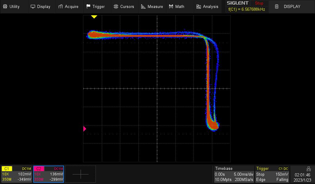
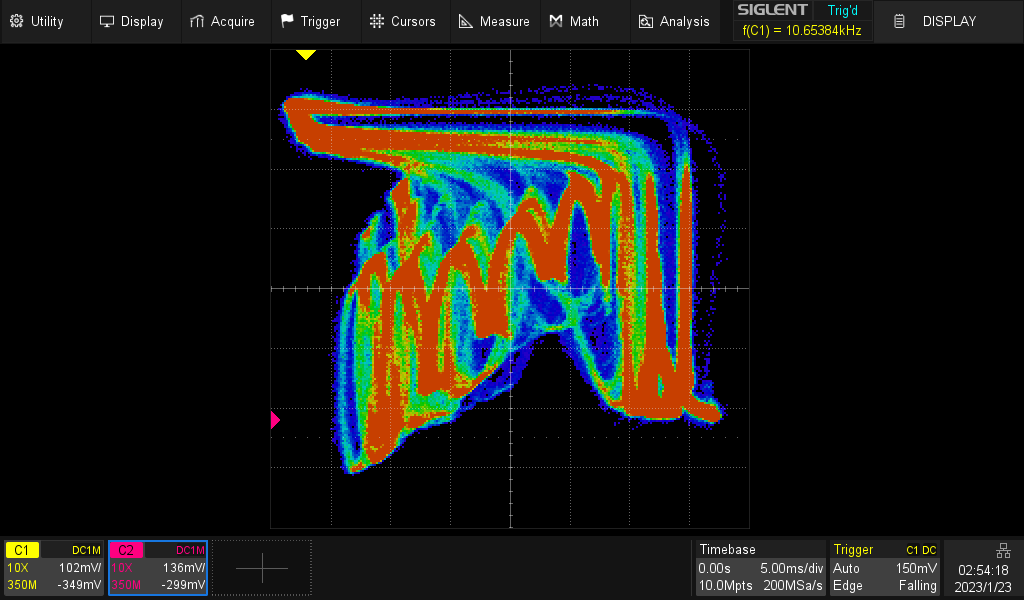
Experienced people always warn noobs like me that in-circuit component measurements are always suspect. It's good advice. For example, if we remove the power supply and attempt to measure the resistance of the pot, we get this:
|
| Yikes!! I created a black hole in my oscilloscope! |
| Or is it a Chaosnado? |
Of course, if we reverse the probes we get no circuit excitation at all. Tricky.
6. References
- Sprott, Julien Clinton, and Wesley Joo-Chen Thio. "Elegant Circuits: Simple Chaotic Oscillators." New Jersey: World Scientific, 2022.
- Check out the chaos in electronics section of my reading list.
- For more about chaos in general, take a look at the fractals section of my reading list.