Mitch Richling: Transistor Switch
How to use a simple transistor as a voltage controlled switch
| Author: | Mitch Richling |
| Updated: | 2023-01-26 |
Table of Contents
- 1. Introduction
- 2. The situation
- 3. The Solution
- 4. Transistor Selection
- 5. Selecting The Base Resister
- 6. Avoiding Excessive Collector Current
- 7. Avoiding Excessive Inductive Kickback
- 8. Avoiding Excessive Base-Emitter Reverse Voltage
- 9. Transistor Heat Sink
- 10. The Load Voltage & Ground
- 11. References
1. Introduction
I get this question quite a bit. Usually someone wants to drive a bright LED via a GPIO pin on an MCU.
2. The situation
A driver circuit with a limited maximum current, \(I_{d(max)}\), needs to switch a load, perhaps at a different voltage level, on and off. Both driver and transistor share a common ground. The load is on when the transistor is saturated, and off otherwise. The transistor is saturated when the load is "high" (\(V_d\)) for the NPN case and when the load is "low" (grounded) in the PNP case.
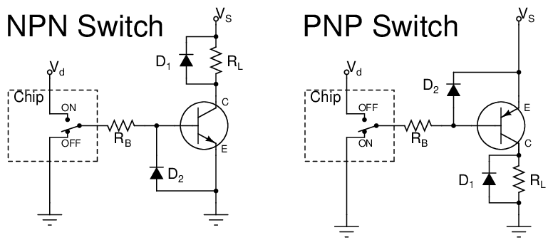
3. The Solution
4. Transistor Selection
The three most sensitive transistor parameters are base saturation current (\(I_{B(sat)}\)), maximum collector current (\(I_{C(max)}\)), and minimum gain (\(h_{FE(min)}\)). For high voltage cases (\(>20\mathrm{V}\)), one must take care not to violate maximum voltage parameters as well. The following three rules will lead to reasonable parameter values for most cases (remember that when saturated, \(I_L \approx V_S/R_L\)):
\[\begin{aligned} I_{B(sat)} < & \,10 \cdot I_{d(max)} \\ h_{FE(min)} > & \,5 \cdot\, \frac{I_{L}}{I_{d(max)}} \\ I_{C(max)} > & \,2 \cdot\, I_L \end{aligned}\]
5. Selecting The Base Resister
\(R_B\) limits the base current to just enough to saturate the transistor. So long as we don't exceed the maximum base current spec (\(I_{B(max)}\)), select \(R_B\) with the following rule:
\[ R_B=\frac{V_d}{5 \cdot I_{B(sat)}} \]
6. Avoiding Excessive Collector Current
If the value of \(R_L\) is very low and the load can be operated at reduced voltage, then place a resistor, \(R_C\) in series with the load. Consider the new load to be \(R_L+R_C\) and proceed as before.
7. Avoiding Excessive Inductive Kickback
If the load is inductive, then the reverse EMF induced at shutoff may destroy the transistor. In this case, the diode, \(D_1\) must be used. For non-inductive loads, \(D_1\) is not required.
8. Avoiding Excessive Base-Emitter Reverse Voltage
If \(V_d\) can be more negative than ground then the diode \(D_2\) may be required to protect the transistor. In most cases this diode is not required.
9. Transistor Heat Sink
The power dissipated by the transistor the is \(P=I_L \cdot V_{CE}\). When the input is at \(V_d\), the transistor is saturated and we have \(V_{CE}\approx0\). When the input line is grounded, the transistor is off, and we have \(I_L = I_C \approx0\). In both cases, \(P\approx0\), so no heat sink is required.
10. The Load Voltage & Ground
When the transistor is saturated the Collector-Emitter resistance is nearly zero (\(R_{CE}\approx0\)), but it is not equal to zero. In the NPN case, the lower end of \(R_L\) will be a couple hundred millivolts above ground. In the PNP case, the top of \(R_L\) will be a couple hundred millivolts below \(V_s\). If this is an issue, then a more complex circuit is required.
11. References
- See the "Engineering: Electrical: Practical Stuff" section of my reading list
- See the "Engineering: Electrical: Circuits & Devices" section of my reading list