Mitch Richling: Servo Signal Generator And Tester
| Author: | Mitch Richling |
| Updated: | 2021-06-08 |
Table of Contents
1. Introduction
The web is cluttered with simple R/C servo testers circuits (mine is here); however, being able to precisely simulate and inject servo signals into live robotics circuits is a more complex matter – for a description of a servo signal look here This capability is particularly important for robotics applications because the device receiving the "servo signal" is frequently not really a servo at all, but a complex sub-circuit that may place much more stringent demands on the signals it receives. A typical pulse generator with external triggering like my BK Precision 4030 will do the trick; however, general purpose test equipment like pulse, data, and arbitrary waveform generators are a bit tedious to use for this application, don't provide transparent circuit integration, and cost too much for most R/C geeks.
2. Requirements
What I wanted on the bench was a "pulse generator" specifically designed for producing the sorts of signals required when troubleshooting servo control circuits. I wanted an easy to use device that could be transparently inserted into, and directly powered by, the circuit under test. The primary mode of operation would be to inject a servo control signal into the device on one side, and have a servo control signal of my choosing come out the other side that is precisely synchronized with the input signal. Sometimes receiver signals have a high frequency sinusoidal voltage of low amplitude superimposed over them, and so it is important to be able lock onto servo pulses in the presence of this kind of noise. Some of my R/C equipment requires that the pulses be clipped at 5V, so that feature was needed too. While my intent was to normally use an external servo signal to set the frequency of the generator, I also wanted the ability to be able to set the frequency to any arbitrary value. When in use, I really wanted to be able to integrate the generator with my function generators, pulse generators, computer, universal counters, oscilloscope, and DMMs. In this way I could visually monitor and precisely measure all signals going into and out of the servo signal generator. Finally, I also wanted to be able to dynamically make ad-hoc circuit changes on the fly – input filters, signal shaping devices, alternate clock sources, etc….
In summary, here is what I was looking for:
- EASY, direct, continuous, analog control over the pulse width (0.2ms - 2.5ms) and frequency (20Hz - 60Hz)
- No interaction between frequency and pulse width – change one and the other stays fixed
- Synchronize with external pulse and servo signal sources to set the frequency – this means providing external triggering on the rising edge of square waves in the face of high frequency, sinusoidal noise and DC offset voltage
- Option to regulate the output servo control pulses to 5V peak
- Must be able to power the tester from the device under test (4V - 15V)
- Easy integration with bench test equipment – oscilloscope, counter, and DMM
- The ability to make ad-hoc changes to the circuit on the bench
- Support high current servos via direct power line bypass – just like the way servos are powered in large aircraft
3. The Finished Device
The two knobs on the front panel provide continuous, and independent, control over signal pulse width and frequency. Typical frequencies for my equipment are marked with dots. The 1.5ms pulse width position is marked with a dot as well. The two switches that control the voltage regulator (clipping servo signal to 5V) and the trigger source (internal or external) are the pull-to-change type that can't be accidentally thrown. The power switch is a safety feature that cuts off main power.
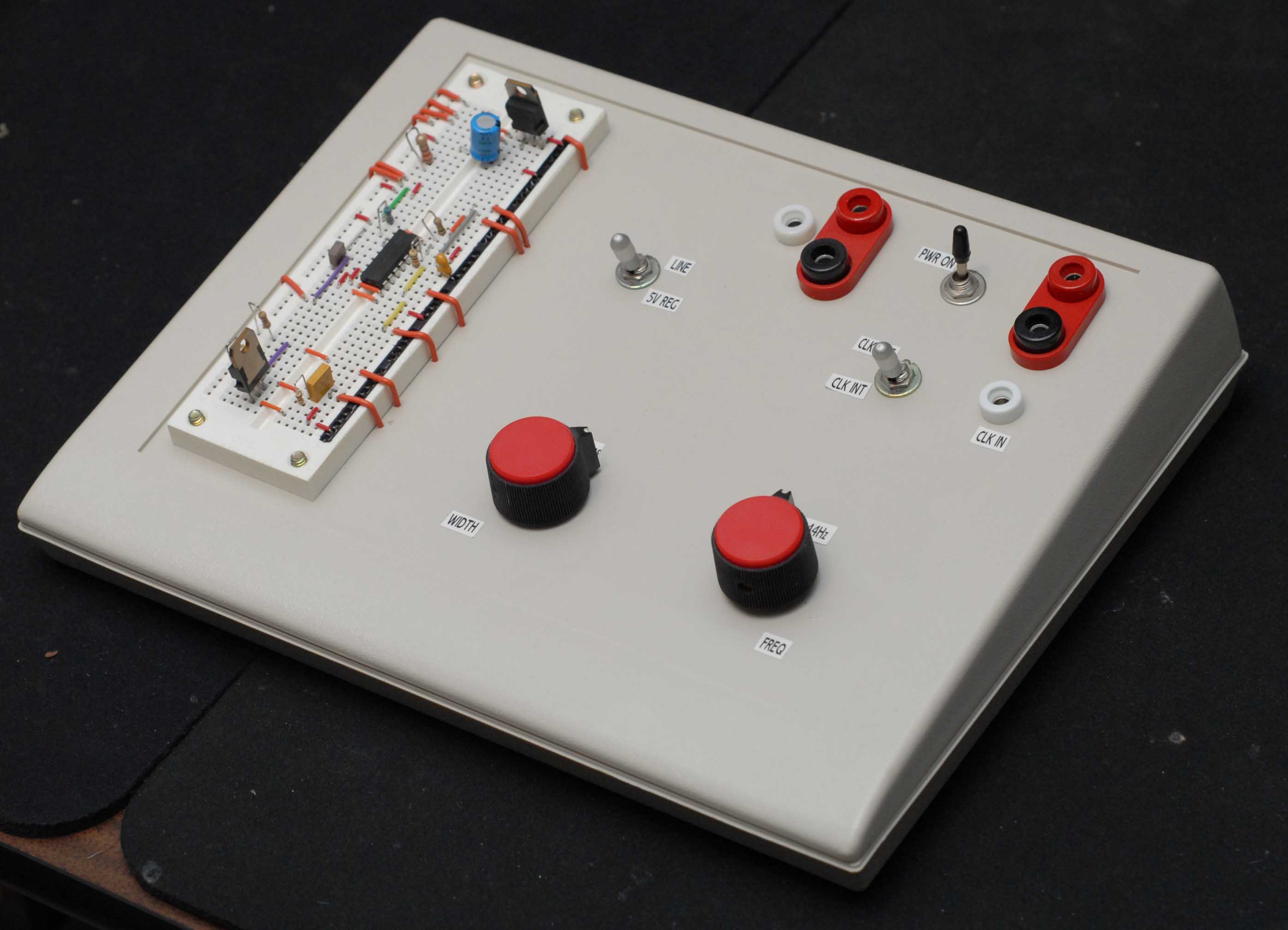
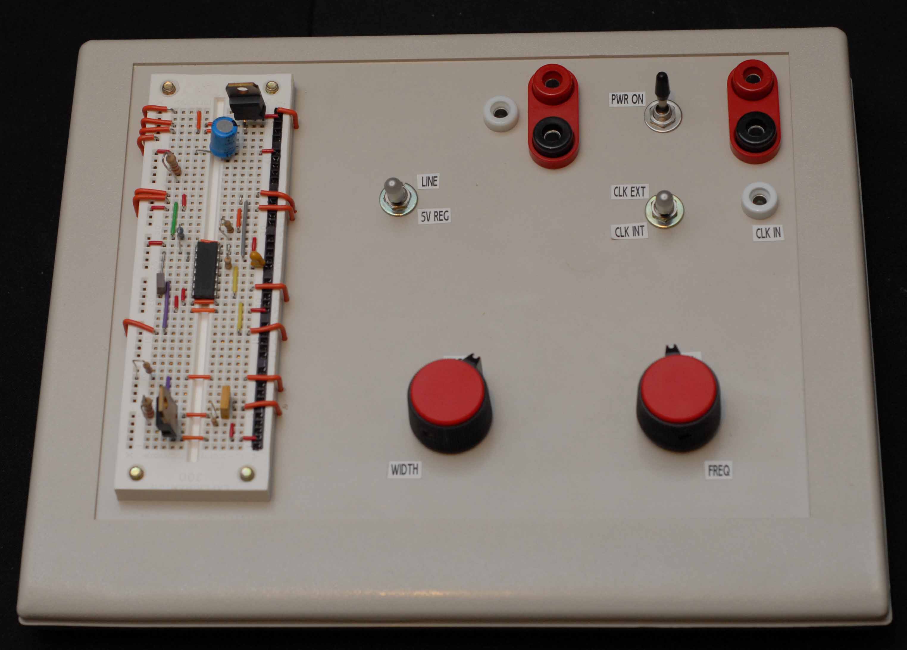
The primary signal lines have been broken out, and made available via banana jacks on the front panel. The banana jacks for power are close together and use large gauge wire to maximize safe current handling capacity for high current servos. As previously mentioned, they are wired in the standard bypass configuration used for high current servos in large aircraft and robots. The power switch is between the pugs to shorten the high current circuit paths in the box. Note also that all the high current wiring is inside the insulating, plastic box. On the back of the unit, a BNC jack exposes the servo signal. All signal lines are solid copper. I have several battery chargers with banana jacks, and so I have several test leads with banana jacks on one end and servo connectors on the other. They use the standard, stranded copper wire found in most servo cables. These test leads, along with standard banana test leads, make for a very easy connections to the rest of the test equipment on my bench. The photo below illustrates some of the test leads I have constructed.
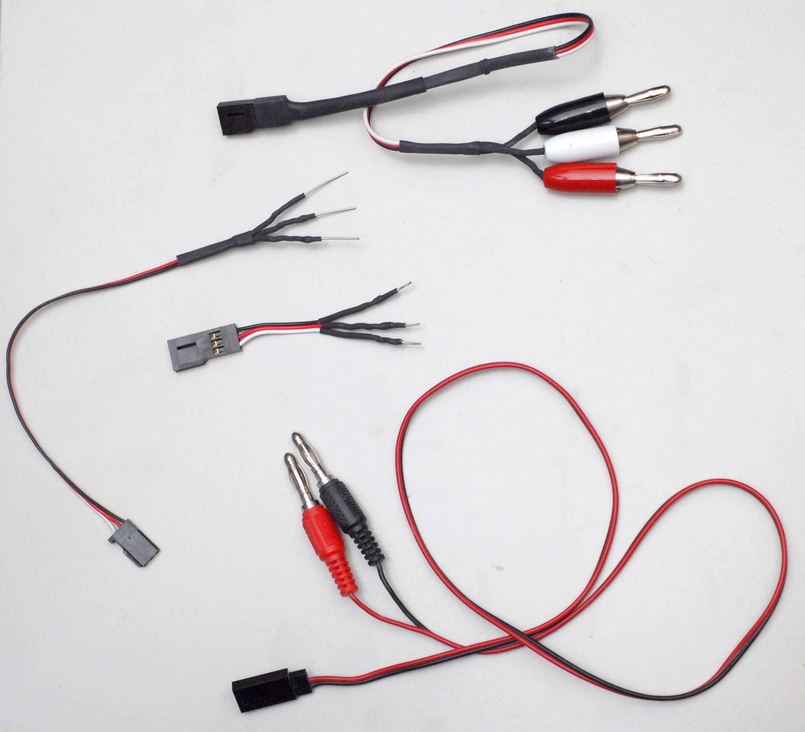
For this project, the most important test lead is the one at the top in the image above. That test lead has three banana jacks at one end and a Futaba servo plug on the other. The servo end is wrapped with heat shrink - three layers near the plug tapering down to one on the wires. This end of the test lead can be abused quite badly when being forcibly pulled from a servo. The other end has a similar treatment with the heat shrink firmly attached inside the banana jack insulating cover. The following image shows this test lead in more detail.

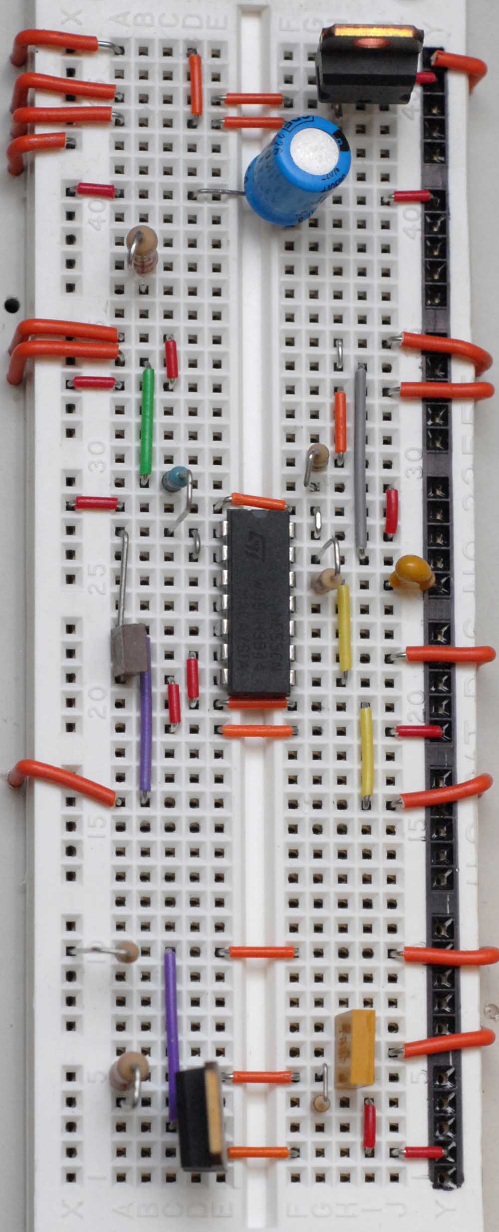
As you can see in the photos, I mounted a proto-board on a project box to facilitate ad-hoc changes. The circuit layout was very carefully deigned to provide
exposed test points for voltage probes as well as signal line break points that can be opened up for the insertion of test equipment. In case you wish to use
my proto-board layout, the image below (click it to get the full sized version) may help. Note that one of the resisters on the board is not connected – it
is a left over from an ad-hoc change. :)
4. The Circuit Diagram
Finally, the last bit you need to build this thing is the circuit diagram (click the image for a PDF):