Mitch Richling: R/C Control Signals
| Author: | Mitch Richling |
| Updated: | 2021-06-08 |
Table of Contents
1. Introduction
Common radio control (R/C from here on out) toys receive radio signals from a transmitter (the "remote control"), and respond accordingly. These radio signals are received by a device on-board the vehicle called, appropriately enough, a "receiver" - usually a tiny box bursting with wires connecting virtually everything electronic on the craft. This page is about the signals between the receiver and the other on-board components it controls - not about the radio signals between the transmitter and receiver. Receivers can control a wide variety of devices including servos, electronic speed controllers, lights, and marshmallow cannons by sending "R/C control signals" to them. The most common device a receiver controls is the servo, and for this reason the signals receivers produce are frequently referred to as "R/C servo signals" - I will use the two terms interchangeably. R/C components have found there way into many electronics devices today, and are especially popular in hobby robotics. In robotics applications these components are most frequently not controlled by a radio receiver, but directly by one of the robot's micro controllers. In order to control R/C components, like servos, the robot hobbyist must replicate the signals the R/C components expect to receive. This page is intended remove the mystery surrounding these control signals, and document precisely what they really look like - for both the budding robot builder and the R/C geek alike.
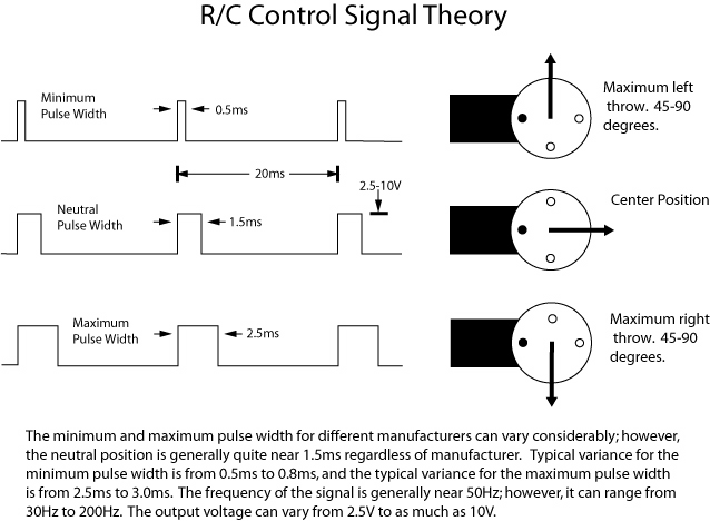
2. Theoretical R/C Servo Signals
Generally speaking the control signal is a square wave pulse train. Common frequencies for control signals are 44Hz, 50Hz, and 400Hz. The positive pulse width is what determines the servo position. A positive pulse width of around 0.5ms will cause the servo horn to deflect as much as it can to the left (generally around 45 to 90 degrees depending upon the servo in question). A positive pulse width of around 2.5ms to 3.0ms will cause the servo to deflect to the right as far as it can. A pulse width of around 1.5ms will cause the servo to hold the neutral position at 0 degrees. The output high voltage is generally something between 2.5 volts and 10 volts (with 3V typical). The output low voltage ranges from -40mV to 0V.
3. Real Examples of R/C Control Signals
Enough with the theory, lets look at some real examples of R/C control signals under ideal conditions. Unfortunately the examples here are not enough to provide a good idea of the variability that is possible across various receivers. In particular, don't look at these images and make the assumption that the neutral point is always 1520 microseconds or that the pulse frequency is aways 44.44Hz. Such assumptions will almost always be violated eventually. Please see the sections below on Generating R/C Control Signals and on Consuming R/C Control Signals for more on this topic.
3.1. Neutral Position
Hitec RCD8200 (Micro 555), 5ch, 72MHz, channel 45, neutral position, aircraft receiver
Futaba FP-R148DF, 8ch, 72MHz, channel 45, neutral position, aircraft receiver
Hitec Electron 6, 6ch, 72MHz, channel 45, neutral position, aircraft receiver
3.2. Transmitter Induced Noise
Note the waveforms have a bit of fuzz at the tops and bottoms. This is because my transmitter is just a few feet away from the receiver. In order to see how bad it can get, consider the following image. This is from the same Futaba receiver pictured above. Note the large fuzzy peaks and valleys?
Waveform showing signal interference
Futaba FP-R148DF, 8ch, 72MHz, channel 45, neutral position, aircraft receiver
Detail of waveform showing signal interference
If we zoom in on the top of one of the pulses, we can see that the "noise" is really a sine wave of 72.98MHz – the frequency of the transmitter. What we are seeing here is cross talk between the receiver's radio circuitry and the receiver's control signal generating circuitry.
4. Generating R/C Control Signals
As motivation, we consider the most common robotics application where an R/C servo is controlled, directly or indirectly, by the robot's brain. In this paradigm the signal is generated by the robot circuitry, and an R/C receiver may not even be part of the design. In this application it is important to understand what characteristics of an R/C control signal are the most important for typical R/C devices - i.e. what aspects we must faithfully duplicate in order to make things like servos operate as expected.
Some R/C devices are particular with regard to what they need, and some experimentation is necessary to get them to work well. For example, with servos the pulse width for a given angular deflection is best determined experimentally with each servo - don't trust the specification sheets, and don't assume that servos of the same model will be identical. That said, some general rules of thumb are possible.
Most R/C devices are relatively immune to the frequency of the control signal, but I generally fix it at around 45Hz for the few devices that seem to care – some helicopter gyros for example. Some R/C devices will self destruct if the maximum pulse voltage is higher than the supply voltage provided to the device – for example, some off-brand, digital servos can be powered at 3.5V, but will be destroyed if the control pulse is at 5V. I generally power R/C devices at 5-18V, and provide R/C control signals at a fixed 3V peak. The low voltage of the control signal doesn't need to be precisely zero, but I normally keep it under 0.1V. In summary:
| Parameter | Range |
|---|---|
| Pulse Maximum Voltage | 3.0V to 3.2V |
| Pulse Minimum Voltage | 0V to 0.1V |
| Neutral Pulse Width | 1500 microseconds give or take 10 microseconds |
| Pulse Maximum | 800 microseconds give or take 10 microseconds |
| Pulse Minimum | 2500 microseconds give or take 10 microseconds |
| Frequency | 44Hz give or take 11Hz |
5. Consuming R/C Control Signals
As motivation, we consider the robotics application where an R/C receiver is used as an on-board "sensor" for the robot. In this paradigm the on-board receiver is not connected directly to anything that it controls, but is connected to the robot's brain. The robot then senses the state of the receiver, and decides what it wants to do about it. It is rather like the difference between driving a car and being a backseat driver. In this application it is important to understand what characteristics of an R/C control signal we can count on.
R/C control signals coming from R/C receivers generally diverge from the ideal in a number of ways. Some of the differences are by design, while others generally arise from using a receiver outside of its design parameters. We shall begin with differences by design.
- Pulse Maximum/Minimum Voltage:
- Some receivers will produce pulses with a maximum voltage very near the power supply voltage feeding the receiver; however, some receivers will clip the maximum pulse voltage at around 3V no matter what the supply voltage is. What you can depend upon is that the maximum pulse voltage will be over 2.5V (assuming your receiver is given at least 4.8V). One can not depend upon the low voltage of the pulse train being 0V, or even being positive. What you can depend upon is that the low voltage will be less than 0.5V. I normally detect the beginning of a pulse by watching for the signal to cross the 2.2V line with a positive slope.
- Neutral Pulse Width:
- One thing you usually can depend upon is the pulse width for a neutral signal being 1500 microseconds give or take 100 microseconds. Still, if you want to be really careful, then you should initialize your code each time with real measurements of "neutral" from the receiver at each power up.
- Pulse Maximum/Minimum Pulse Width:
- You can't really depend upon these values at all. They should be measured for each receiver/transmitter combination used, and any micro-controller code should have previsions for adjusting the values. One option I generally use is to have an initialization mode that allows me to move the stick on the transmitter to max/min positions, and let the robot measure the resulting values along with neutral.
- Pulse Width Resolution:
- The resolution, or minimum step change, in pulse width possible is quite variable across receiver/transmitter combinations. You can find resolutions as high as 2 microseconds and as low as 100 microseconds. It is best to determine what resolution you need, and then design your sample rate accordingly instead of using a theoretical maximum.
Now we consider some of the bad things that can happen when we push R/C receivers too far outside of their design envelope. Unlike the previous difficulties, these problems are more difficult to deal with. In particular, most of these difficulties can not be remedied by simple micro-controller software patches, and require real hardware changes. Sometimes this can be as simple as moving an antenna or shielding some electronics.
- Drawing too much current
- R/C receivers are not designed to deliver much current, and doing so can have some unfortunate consequences. In the worst case, the receiver will be destroyed. In the best case, the waveform will simply be distorted. The most common distortions are slow rise times, slow fall times, or voltage swings that don't quite make it up to 3V.
- Too much LF electrical noise
- Some older R/C receivers are designed to work in the relatively noise free environments of gas powered R/C aircraft and boats. Modern brushless motors in R/C cars and aircraft can generate far too much low frequency electrical noise for such receivers. The most common symptom is control signal waveform distortion in the form of voltage spikes, runt pulses, or jitter in the pulse width. Diagnoses without a oscilloscope is difficult, but a common symptom is what R/C geeks call "twitching servos".
- Too much HF electrical noise
- Most R/C receivers are designed to work in environments relatively free of high RF noise. This is especially true of RF that is at the same frequency the receiver is designed to receive. For example, a 70MHz CPU running near a 72MHz receiver will almost always lead to the receiver being unable to pick up the signal from the transmitter. The most common symptom is loss of connectivity between the transmitter and receiver - sometimes intermittent.
- Transmitter signal too strong
- Most R/C receivers are designed to pick up faint signals from low power R/C transmitters at ranges of 1 mile. If the signal form the transmitter is too strong, it can lead to strong interference being coupled onto the R/C control signals coming out of the receiver. The best way to diagnose the problem is to look at the R/C control signals coming out of the receiver with an oscilloscope. Look for a sine wave the same frequency as your transmitter overlaid on top of the normal R/C control signal. See the image here for an example of what it looks like. Without an oscilloscope, this is almost impossible to diagnose. Look for "twitching servos" and intermittent loss of transmitter/receiver contact.
- Poor supply power
- Many R/C receivers are not tolerant of quick power supply voltage variations. For example the types of spikes that are common in digital circuits can cause all sorts of receiver problems. For this reason it is a good idea to put a big capacitor across the supply terminals of a receiver if it is used in a larger circuit.
6. R/C Control Signal Generator Circuit
Simple servo testers can be built out of one 555 timer IC and a few passive components for less than one dollar. While this kind of tester can provide good control over pulse width, the pulse frequency changes as the width is adjusted. The circuit presented here makes use of a 556 IC (essentially two 555's) to provide independent control over both frequency and pulse width of the test signal. A good DMM or oscilloscope can be used to fine tune an monitor the pulse width and frequency. Note that the output pulses have a maximum voltage equal to the input voltage of the circuit. This can be a problem if your servos expect a 3V control signal. You might also be interested in a more sophisticated circuit and servo tester project.